Introduction
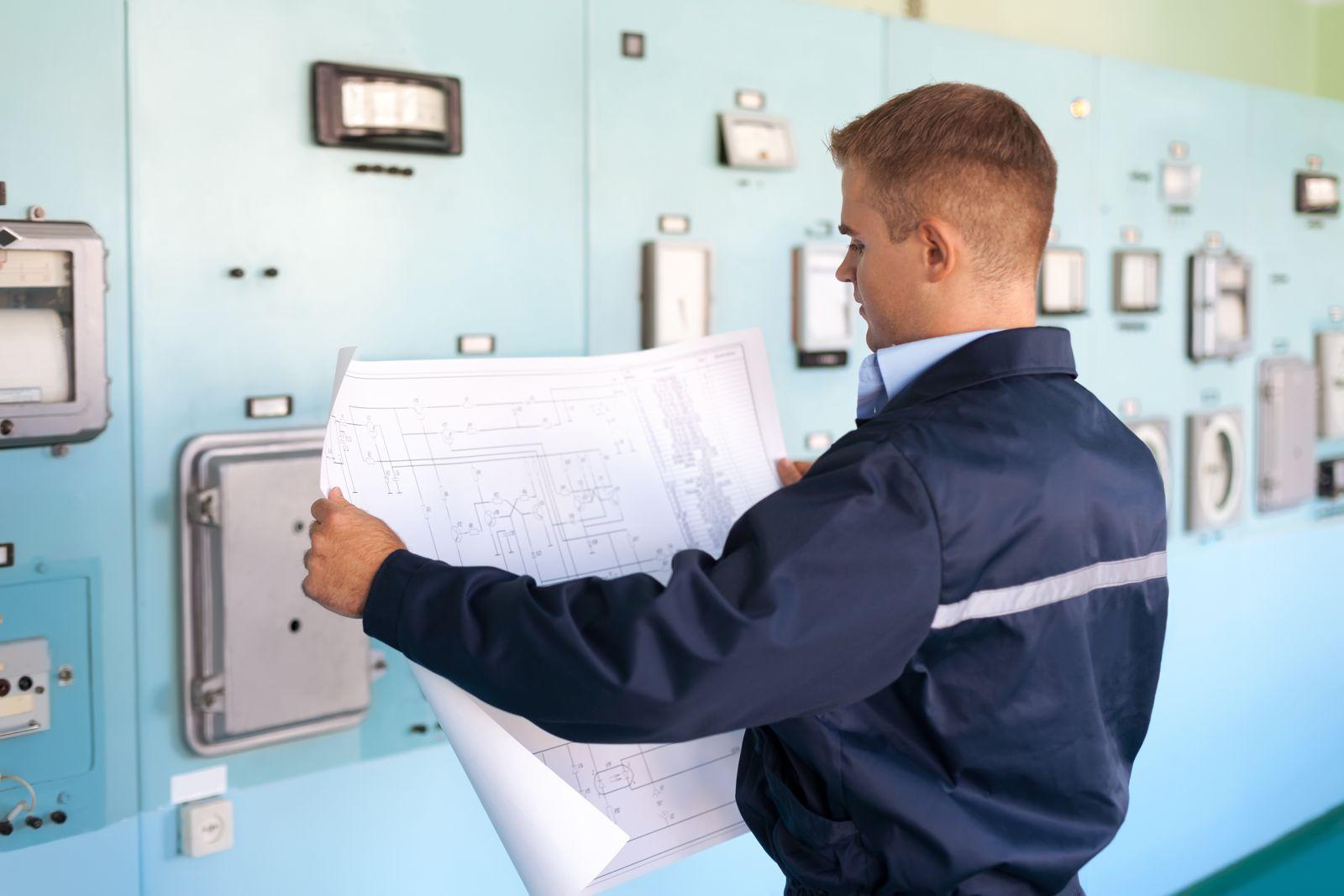
A riser diagram is a drawing that shows how a building system is distributed vertically, floor by floor. An electrical riser diagram shows the service at the bottom, the panels and transformers on each level and the feeders that climb between them. It is drawn without a scale, so it shows what connects to what and on which floor, and it leaves the lengths to be worked out.
Estimators work them out by hand. They take each feeder's size from the feeder schedule, add up floor-to-floor heights from the building sections, and add the horizontal runs measured on the floor plans.
On a tall building or a multi-level process structure that is dozens of feeders, each with its own arithmetic, and fewer estimators are carrying more bids. Feeders are the heaviest copper on the job, so a floor height left out of ten feeders is a real sum.
This guide covers what the diagram shows, how it differs from a single line diagram, six steps for going through it and a worked feeder length example.
157+ electrical estimators say The Takeoff AI saves them 90% of their estimating time. Plans are on The Takeoff AI pricing page.

What an Electrical Riser Diagram Shows
An electrical riser diagram shows the distribution equipment on each floor and the feeders that connect it.
- It shows the service entrance and main switchboard, usually at the lowest level.
- It shows the panels, transformers and disconnects on each floor, by name.
- It shows each feeder with a tag or a callout for its wire and conduit size.
- It shows the generator, transfer switches and any bus duct that runs up the building.
Riser Diagram vs Single Line Diagram
A riser diagram is organized by floor, and a single line diagram is organized by the electrical order from source to load.
| Riser Diagram | Single Line Diagram | |
|---|---|---|
| Organized By | Floor or level | Electrical order |
| Shows | Where equipment sits and how feeders route | Ratings, protection and voltages |
| Used For | Feeder lengths and conduit takeoff | Equipment counts and ratings |
| Most Common On | Multi-story commercial buildings | Industrial and large commercial projects |
Many sets include both, and the companion guide covers how to read a single line diagram.

How to Read a Riser Diagram, Step by Step
Go through a riser diagram from the service upward, one feeder at a time.
- Find the service and the main gear at the lowest level.
- Follow each feeder up the sheet and note its tag.
- Match the tag to the feeder schedule for the wire size, conduit size and number of parallel sets.
- Note the equipment each feeder lands on and its floor.
- Take the floor-to-floor heights from the building sections or an elevation drawing.
- Add the horizontal runs at each end from the floor plans.
Worked Example: Feeder Length From a Riser Diagram
A panel on level 4 is fed from a switchboard in the basement with four 1/0 wires and a ground. The basement-to-level-1 height is 14 feet and each floor above is 12 feet, so the vertical rise to level 4 is 14 plus 36, which is 50 feet. The floor plans show 35 feet of horizontal run in the basement and 20 feet on level 4.
The conduit length is 50 + 35 + 20 = 105 feet. Allowing 10 feet of extra wire at each end for the terminations, each wire is 125 feet, so the takeoff carries 500 feet of 1/0 and 125 feet of ground wire. Long vertical runs also need wire supports under the National Electrical Code (NEC) Section 300.19, which adds material and labor.
Other Riser Diagrams in a Drawing Set
Electrical sets often carry separate risers for fire alarm, telecommunications and grounding, and each one is taken off the same way. The plumbing riser diagram belongs to another trade and shows pipe, not conduit. On industrial projects the same information often appears as cable tray layouts with elevation callouts at each level of a process structure.
Common Mistakes
Three mistakes cause most feeder length errors.
- The riser is scaled with a ruler, when the sheet is marked not to scale.
- One conduit is counted where the schedule calls for two or more parallel sets.
- The vertical distance between the ceiling space and the top of the panel is left out at each end.
How The Takeoff AI Handles Feeders and Risers
The Takeoff AI estimates from your electrical drawings, counts the panels on every level and measures the conduit and cable between them by size. The electrical takeoff Handbook page explains how conduit, cable and cable tray get counted.
The Takeoff AI is built on AI models trained on more than 1.2 million electrical and instrumentation (E&I) drawings. It counts devices, panels and fixtures, measures conduit, cable and cable tray lengths, splits the cable between tray and conduit, and picks up instruments from the instrument index. It delivers 95% accuracy, and every number is marked and highlighted on the drawing it came from, so someone can check it before the bid goes out.
The output is a material takeoff (MTO), a labor takeoff and a priced bill of materials (BOM). Estimators using it finish projects in 2 to 3 hours that used to take 30 to 40 hours, which saves 90 to 95% of their estimating time, and 157+ electrical estimators say The Takeoff AI saves them 90% of their time. It covers piping, piping and instrumentation diagrams (P&IDs), isometrics, mechanical, electrical and instrumentation, plumbing, HVAC including ductwork, structural steel, misc iron and concrete.
One customer, Joshua Nelson, Principal of Nelpro Project Solutions, saves 95% of estimation time with The Takeoff AI, and his packages of more than 200 drawings across four disciplines come back in hours, where the same work used to take weeks.
Book a demo of The Takeoff AI.
Fewer Electrical Estimators, More Bids
The Bureau of Labor Statistics (BLS) counts about 221,400 cost estimators in the US and projects a 4% decline in that number by 2034, and roughly three in four estimator seats will need to be refilled over the decade, as The Shortage of Estimators report sets out. Feeder lengths are still added up floor by floor on paper in most electrical estimating departments, and that can't hold with fewer estimators carrying more bids. Electrical contractors moving into data center work feel this first, as The Data Center Boom Has A Problem explains, and The Takeoff AI suits firms expanding into data centers.
FAQs
What Is a Riser Diagram?
A riser diagram is a drawing that shows how a building system is distributed vertically from floor to floor. An electrical riser diagram shows the service, the panels on each level and the feeders between them.
What Is the Difference Between a Riser Diagram and a One Line Diagram?
A riser diagram is arranged by floor and shows where equipment sits and how feeders route. A one line diagram is arranged in electrical order and shows ratings, voltages and protection.
Is a Riser Diagram Drawn to Scale?
No, a riser diagram is a schematic and is not drawn to scale. Feeder lengths come from floor-to-floor heights on the sections or elevations plus horizontal runs measured on the floor plans.
What Is a Fire Alarm Riser Diagram?
A fire alarm riser diagram shows the fire alarm control panel, the devices or device counts on each floor and the circuits that connect them. Estimators use it with the floor plans to count devices and measure cable.
How Much Time Does The Takeoff AI Save on an Electrical Estimate?
157+ electrical estimators say The Takeoff AI saves them 90% of their time. Projects that used to take 30 to 40 hours are finished in 2 to 3 hours, with a material takeoff, a labor takeoff and a priced bill of materials at the end.
How Do I Check an AI Electrical Takeoff Before I Bid?
Every number in The Takeoff AI is marked and highlighted on the drawing it came from. The estimator opens any quantity, sees its source on the sheet and corrects it before the bid goes out.
Conclusion
A riser diagram shows where every feeder goes, and turning it into lengths is arithmetic that someone has to repeat for each one. The work has stayed manual, and it can't stay that way with fewer electrical estimators carrying more bids. The Takeoff AI is the best electrical estimating software for contractors who need the takeoff done and priced in hours.