Flange Bolt Chart
ASME B16.5 and B16.47 flange bolt chart. Stud bolt diameter, quantity, and length by pipe size and pressure class, RF and RTJ, plus how theTakeoff derives every bolt set from the P&ID.
Live today. theTakeoff reads the P&ID, finds every flanged joint, and pulls the bolt kit from these same tables.
Every member tagged, measured, and traced back to the sheet it came from.
Three things fix the bolt set on every flange
None of them is a judgment call. Once you have the pipe size, the pressure class, and the facing, the flange bolt size by flange size is a table lookup. The tables are further down this page. theTakeoff does the lookup for every flanged joint on the drawing and shows the row it used.
Nominal pipe size sets the bolt circle
Bigger pipe means a bigger flange, a wider bolt circle, and more holes. A 2" Class 150 flange takes four 5/8" studs. A 24" Class 150 flange takes twenty 1-1/4" studs. The jump is not linear, which is why the flange bolt dimensions chart exists.
Pressure class sets the bolt diameter and count
Higher classes carry thicker flanges and tighter spacing, so the flange bolt diameter and quantity both climb. A 6" flange uses eight 3/4" studs at Class 150, twelve 1" studs at Class 600, and twelve 1-1/2" studs at Class 2500. Same pipe, double the bolt diameter.
Facing sets the stud length
Raised face and flat face share one bolt pattern. Ring type joint flanges are thicker because of the ring groove, so the studs run 3/4" to 1-1/2" longer at the same size and class. The RF flange bolt chart and the RTJ flange bolt chart below list both.
Bolt sizes straight from ASME B16.5 and B16.47
A bolt set typed from memory is a bolt set that is wrong on install day. theTakeoff reads the flange size and class off the line designation table and resolves the stud bolt against the ASME B16.5 flange bolt chart, so an 8" Class 300 flange comes through as twelve 7/8" studs at 5-1/2" every time. Above 24" it switches to the ASME B16.47 flange bolt chart. The number comes out of the published table, not out of last year's spreadsheet.
- Stud bolt diameter, count, and length keyed to B16.5 Tables 7C through 12C
- Class 150, 300, 600, 900, 1500, and 2500 handled by class
- Series A and Series B large-bore flanges handled by series
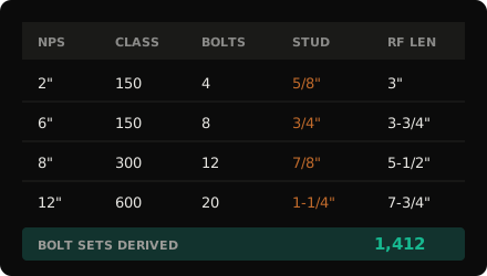
Illustrative example. Bolt sets resolved from the flange, not hand-typed.
Click any bolt set, see the flange it came from
A P&ID draws a flanged joint as two parallel lines. It does not show the bolt, the size, or whether the facing is RF or RTJ. All of that lives in the piping spec, reached through the line class. theTakeoff makes that cross-reference for every joint and keeps the trail: the sheet, the line number, the class, and the B16.5 table row that produced the flange bolt kit.
The estimator still owns the number that goes in the bid. The tool takes the lookup off the desk and leaves a trail you can defend when a spec break changes the class mid-line.
- Every bolt set links to its flange, line number, and source sheet
- Change a class in one click and every downstream bolt set updates with the audit trail
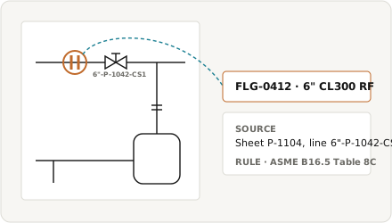
Illustrative example. Click a bolt set, land on the flange.
Thousands of flanges. One chart. Zero room for a wrong row.
A refinery turnaround package can run 300 P&IDs and several thousand flanged joints, across mixed classes and mixed facings. Each one needs a bolt set, and each bolt set comes from a row on a flange bolt chart. Done by hand, that is thousands of lookups against a printed table, and the errors hide until the crew is short on 1-1/4" studs at six in the morning. Software that derives the bolt set from the drawing removes the lookup, and the error that rides with it.
The flange count is step one. The bolt kit behind every flange is where the hours and the mistakes go.
Trusted by 200+ enterprises across EPC, Infrastructure, and Energy











Reference The Estimating Library
Practical takeoff references, charts, and workflow guides, built for working estimators.
P&ID Symbols and Meanings: The Complete Legend
The symbols on a P&ID explained: piping and instrumentation diagram symbols for equipment, lines and signals, valves, and the instrument bubbles and tags, plus what an estimator counts off one.
Piping Isometric Drawing Software: What It Does and How to Choose
Here's the "piping isometric drawing software" entry, in your Handbook fields. I wrote it US-lexicon from the start (bid, not tender) and kept it honest about what theTakeoff actually is, since this search term is really about isometric drawing software and your product reads isos rather than drawing them, so it sits in the piping takeoff software category.
45 degree elbow take off chart
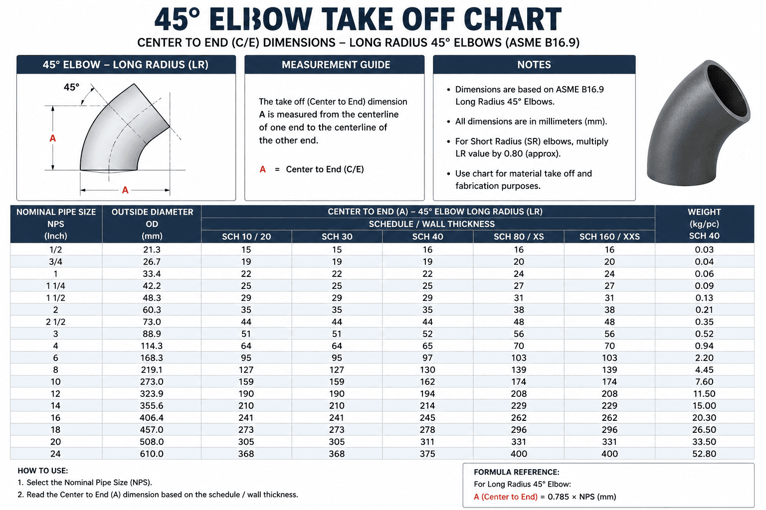
The 45° Elbow Take-Off Chart is a piping reference used by engineers, estimators, and fabricators to determine the center-to-end (take-off) dimension of long-radius 45° elbows. It lists dimensions based on nominal pipe size (NPS) and pipe schedule, enabling accurate pipe cutting, layout, and material estimation. The chart helps ensure proper fit-up during fabrication while reducing measurement errors and material waste.
Flange Bolt Chart
How many bolts does a flange have?
An ASME B16.5 flange has 4, 8, 12, 16, 20, or 24 bolts depending on pipe size and pressure class, always a multiple of four. Small sizes up to 1-1/2" at Class 150 use four. A 24" at Class 300 uses twenty-four. The exact count for every size and class is in the flange bolt chart on this page.
What size bolts for a 6 inch 150 pound flange?
Eight 3/4" stud bolts. The raised face stud length is 3-3/4", the RTJ length is 4-3/4", and the bolt circle is 9.50". Those figures are from ASME B16.5 Table 7C.
Is an ANSI flange bolt chart the same as an ASME flange bolt chart?
Yes. ANSI first published the flange dimensions and ASME maintains them now. The current edition is ASME B16.5-2020. An ANSI flange bolt chart and an ASME B16.5 flange bolt chart give the same stud bolt sizes, counts, and lengths. Older prints and specs still say ANSI.
How is stud bolt length calculated for a flange?
For standard B16.5 flanges with standard RF or RTJ facings, use the chart length. For a non-standard stack such as an insulation kit or a spacer ring, stud bolt length is two flange thicknesses plus the gasket, plus two nut heights, plus stick-through, rounded up to the next standard increment, 1/4" below 10" and 1/2" above.