P&ID · How to read
P&ID Symbols and Meanings: The Complete Legend
Short answer
P&ID symbols are the standard shapes and tags on a piping and instrumentation diagram that show the equipment, the piping and signal lines, the valves, and the instruments and control loops. They fall into four groups: equipment symbols for vessels, pumps and exchangers, line symbols for process piping and for pneumatic, electric and data signals, valve symbols for the different valve types, and instrument bubbles with tags that follow ANSI/ISA-5.1. Read the bubble for where the instrument sits and read the tag for what it measures and does. The drawing legend is the final word, because projects vary.
- P&ID symbols split into equipment, lines and signals, valves, and instruments.
- P&ID symbols split into equipment, lines and signals, valves, and instruments.
- Instrument tags follow ANSI/ISA-5.1: the first letter is the measured variable, the letters after it are the function.
- Instrument tags follow ANSI/ISA-5.1: the first letter is the measured variable, the letters after it are the function.
- The line through an instrument bubble shows where it is mounted and who can reach it.
- The line through an instrument bubble shows where it is mounted and who can reach it.
- Valves are drawn as a bowtie, with the type shown by what sits in or on it.
- Valves are drawn as a bowtie, with the type shown by what sits in or on it.
- The legend sheet defines the exact symbols for that project. Always read it first.
- The legend sheet defines the exact symbols for that project. Always read it first.

What is a P&ID and why the symbols matter
A piping and instrumentation diagram, or P&ID, shows how a process is put together: the equipment, the piping that connects it, the valves that control the flow, and the instruments and control loops that run it. It does not show real lengths or scale. It shows logic, unlike a process flow diagram, or PFD, which stays high level. The whole thing is drawn in symbols, so reading a P&ID is reading its symbols and their meanings. If you are learning how to read a P&ID, this guide is a plain-language legend of the common piping and instrumentation diagram symbols and their meanings, and how to use them. For an estimator the P&ID is where the valve counts, the instrument counts, the equipment and the line list come from, so the symbols are not trivia, they are the takeoff.
The four symbol groups
Everything on a P&ID falls into one of four groups, the four types of P&ID symbols you will meet. Equipment symbols show the vessels, tanks, columns, pumps, compressors and heat exchangers, drawn as recognizable schematic shapes. Line symbols show the piping and the signals, with different line styles for a process pipe, a pneumatic signal, an electric signal and a data link. Valve symbols show the valve types, drawn as the bowtie and its variants. Instrument symbols, the bubbles and tags, show what is measured and controlled and where the instrument sits. Learn to sort a symbol into its group first, then read the symbol and its meaning.
Line and signal symbols
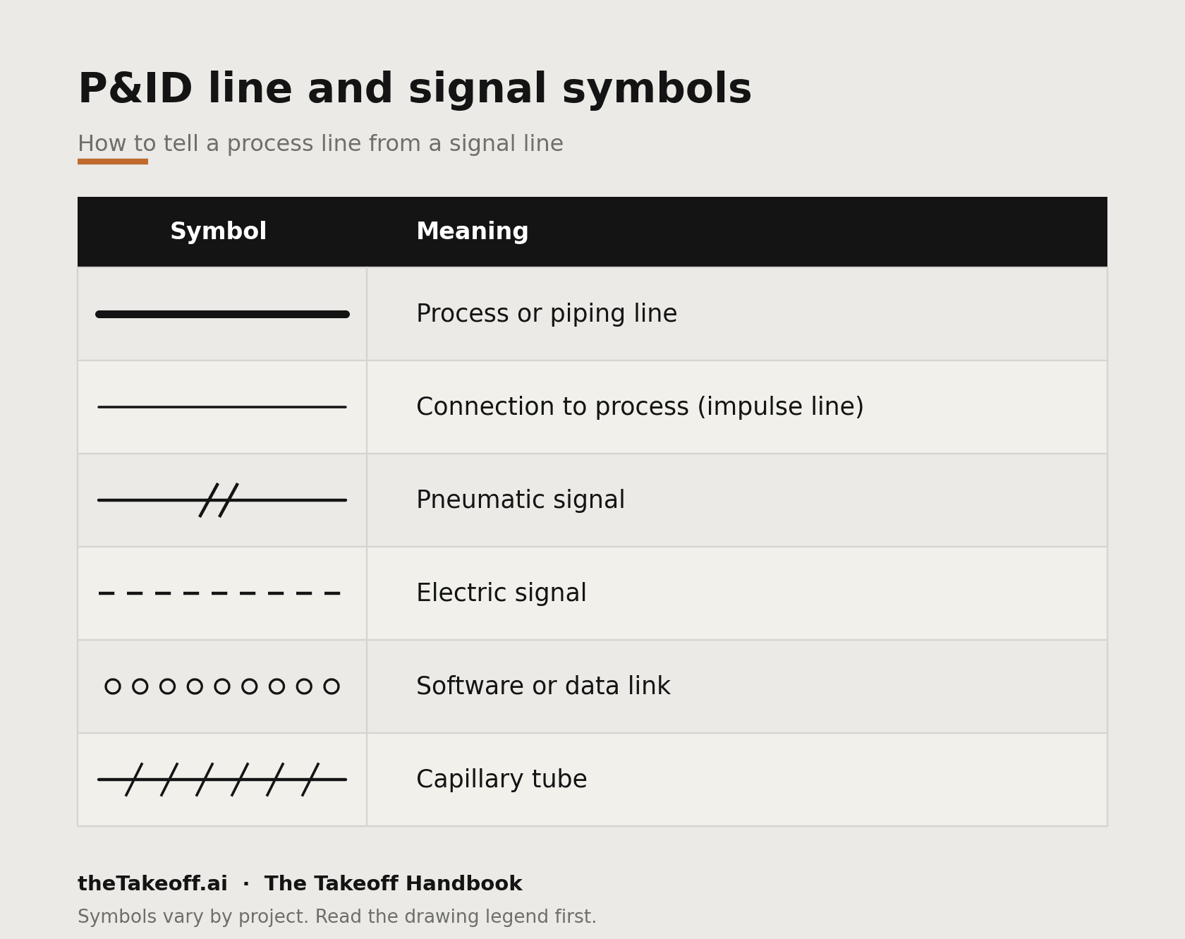
These P&ID line and signal symbols separate the piping from the signals at a glance. The process piping is drawn as a heavy solid line, and the line number tells you its size, service and class. The signal lines are thinner and coded by pattern. A connection to the process, the impulse line, is a thin solid line. A pneumatic signal is a line with double crosshatch marks. An electric signal is a dashed line. A software or data link inside a control system is a line with small circles or dots. A capillary is a line with crosshatch. The pattern tells you what kind of signal it is, which tells you the instrument type feeding it, so each line style has a clear meaning.
Equipment symbols
Equipment is drawn as a simplified picture of the real thing. A vessel or drum is a capsule or cylinder, a column is a tall vessel with internals shown, a pump is a circle with a triangle, a compressor has its own outline, and a heat exchanger is a shell with tubes or a circle with the flow paths. Each piece carries an equipment tag, for example a pump P-101 or an exchanger E-201, and often a duty or size note. You read the shape for what it is and the tag for which one it is.
Valve symbols
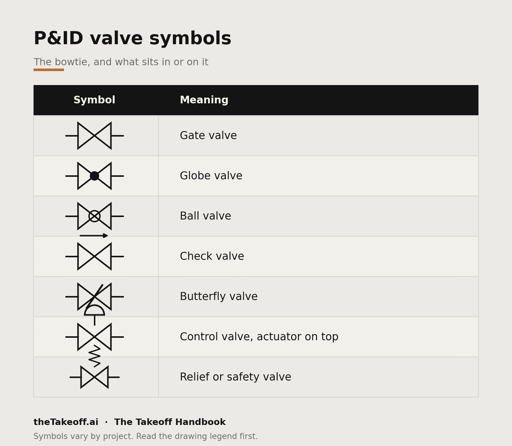
Valves are drawn as a bowtie, two triangles meeting at a point, with the type shown by what sits in the middle or on top. These are the common P&ID valve symbols you will see across projects.
A control valve carries an actuator symbol on top that tells you how it is driven: a dome or bell for a diaphragm actuator, a rectangle for a piston, a circle with M for a motor, and a small box with S for a solenoid. The actuator matters for the count, because a control valve with its actuator, positioner and tubing is a different item from a plain manual valve. The control valve symbol can vary slightly by project, so always confirm it in the drawing legend.
Instrument bubbles and how to read them
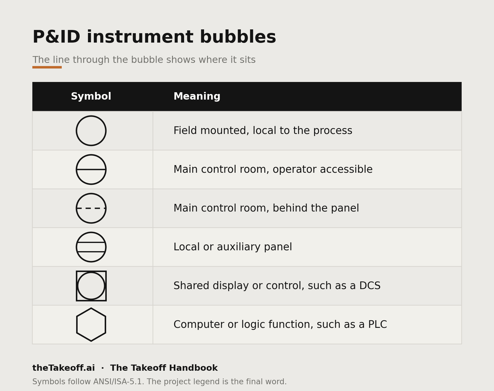
An instrument is a circle, called a bubble. The line through the bubble tells you where it sits and who can reach it.
The tag inside the bubble is the other half. Read it and you know what the instrument does. These are commonly called P&ID instrument tags on drawings and in specifications.
The instrument tag, decoded
Instrument tags follow ANSI/ISA-5.1. The first letter is the measured or initiating variable, and the letters after it are the function.
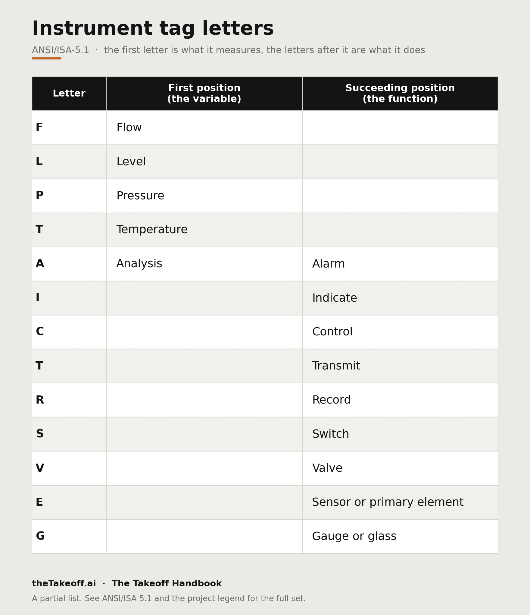
So FT is a flow transmitter, FIC is a flow indicating controller, LG is a level gauge, LSH is a level switch high, PT is a pressure transmitter, TIC is a temperature indicating controller, and PSV is a pressure safety valve. Add the loop number and you have the full tag, for example FIC-101. Read the first letter for what it senses and the rest for what it does with it.
Reading a P&ID for a takeoff
For estimating, the P&ID is the bid-stage source. It does not carry lengths, but it carries the counts. Off a P&ID you take the valve count by type and size, the instrument count by type off the bubbles and tags, the equipment list off the equipment symbols, the specialty items, and the line list with the size, service and class for each line. You itemize the high-value items, the valves, instruments and equipment, straight from the symbols and the schedules, and you carry the line list into the isometric stage for the lengths and bulk material. Miss a control valve station or read a spec break wrong and the count is off before pricing starts.
Common mistakes reading P&ID symbols
The usual ones: reading a control valve as a plain valve and missing the actuator, positioner and tubing that go with it, misreading the bubble line and putting an instrument in the wrong location class, reading only the first letter of a tag and missing the function, and trusting a symbol from memory instead of the drawing legend, which is where the project defines its exact set. Signal lines get skimmed too, and the signal type tells you the instrument type.
Where theTakeoff fits
theTakeoff reads P&IDs and pulls the counts off the symbols and the tags. It lists the valves by type and size, the instruments by type off the bubbles, the equipment, and the line list with each line's size, service and class, and every count links back to the symbol on the drawing. The estimator checks the count against the sheet instead of building it by hand, and owns the number that goes in the bid.
FAQ
Q: How do you read an instrument tag on a P&ID?
A: The first letter is the measured variable, such as F for flow or L for level, and the letters after it are the function, such as I for indicate or C for control. FIC is a flow indicating controller. These conventions appear in P&ID instrument tags per ANSI/ISA-5.1.
Q: What does the line through an instrument bubble mean?
A: It shows where the instrument is mounted and who can reach it, from field mounted with no line to control room mounted with a solid or dashed line.
Q: How is a control valve shown on a P&ID?
A: As a valve body with an actuator symbol on top, a dome for a diaphragm, a rectangle for a piston, a circle with M for a motor, or a box with S for a solenoid. Check your legend for the exact control valve symbol P&ID standard used on the project.
Q: Do P&ID symbols follow a standard?
A: Instrument symbols and tags follow ANSI/ISA-5.1, but each project has a legend sheet that defines its exact set, so read the legend first.
The P&ID symbols legend?
P&ID stands for piping and instrumentation diagram, the drawing that shows the process: the equipment, the piping, the valves, and the instruments and control loops.
What do P&ID symbols mean?
They represent the equipment, the piping and signal lines, the valves, and the instruments on the drawing. A bowtie is a valve, a circle is an instrument, and the line style separates a process pipe from a signal.
Is there a P&ID symbols legend or chart?
Yes. Every drawing set carries a legend sheet that defines its exact symbols, and it is the final word for that project. The valve, instrument and line legends on this page cover the common ones.
What are the most common P&ID symbols?
The valve bowtie and its variants, the instrument bubble, and the line styles for process, pneumatic and electric signals. Equipment is drawn as a simplified picture of the real item.
How do you read P&ID symbols?
Sort each symbol into equipment, line, valve or instrument, then read the detail: the valve type from what sits in the bowtie, the instrument from the bubble and its tag, and the signal from the line style.
What is the difference between a P&ID and a PFD?
A PFD, or process flow diagram, shows the process at a high level with the main equipment and streams. A P&ID shows the detail: every line, valve, instrument and control loop.